
Blynk is an IoT-platform that consists of a Blynk server, custom projects within an iOS/Android mobile app and custom hardware IoT-nodes (Arduinos etc) using a Blynk library. The mobile app communicates with the hardware via the Blynk server and you can use the mobile interface for displaying sensor data from the hardware nodes or control actuators on the nodes.
You can use the cloud version of the Blynk server or host your own instance. In this post, I will show how I have setup a Blynk server on a Raspberry Pi and how I am using it for mobile communication with an ESP32 board that is developed with PlatformIO for Atom.
The ESP32 hardware
I have a couple of brand new Geekworm ESP32 development boards that I want to use. For this example, I have connected a DHT11 temperature/humidity sensor and an active piezo buzzer to the board:
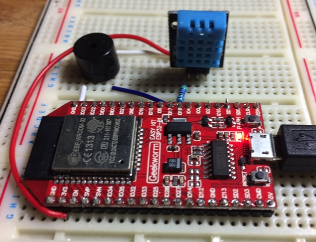
The idea is that the sensor data should be available via a mobile app, and that the mobile app should be able to trigger a beep on the buzzer that is connected to the ESP32.
The Blynk server
The Blynk server handles the communication between the mobile application and the hardware IoT-board. There is a cloud version of Blynk that can be used, but I’m opting for running my own server on a Raspberry Pi.
The Blynk server is a jar-file that requires Java 8. After downloading the jar-file (server-0.26.1.jar in my case), the Blynk server can be started with:
java -jar server-0.26.1.jar
When the server starts, a message stating the default credentials appears:
Your Admin login email is admin@blynk.cc
Your Admin password is admin
You can log in to:
https://<IP OF MACHINE RUNNING BLYNK>:9443/admin
with these default credentials and then go to the users list and change them.
The Blynk app
The Blynk app can be downloaded for iOS or Android. In this tutorial, I will use the iOS-version. I will setup a Blynk project with a button and a value display. The project will work with an ESP32 dev board via WiFi.
When the Blynk app starts, you have to log in. If you have setup your own Blynk server as described above, specify your user email and password, select custom server and specify the IP of the machine that is running the Blynk server (with port 8443). In my case the IP of my Raspberry Pi on the local LAN, 192.168.1.16:

Now you can login and create a new project:

In the project area, swipe from the right to show the list of available widgets.

I’m going to create the buzzer/beep button first, so select a button widget. In the project area, double click the button to show its settings. Give the button a name and connect it to virtual pin V1:

Next, create a Value Display widget. Give the widget a name, connect it to virtual pin V2 and select refresh interval = Push. Push means that the hardware node will send updated values to the server at regular intervals. An alternative is to let the mobile app poll for values at regular intervals.

Before coding the hardware node, we need the authentication token for this project. Go to the project settings and check the auth token:

This token needs to be pasted into the code that we upload to the ESP32-board.
The next step is to add the code for the hardware node. Before that I will briefly cover PlatformIO that I am using for development.
PlatformIO
I’ve started to use PlatformIO instead of the Arduino IDE for most of my IoT-projects. The Arduino IDE is great in its simplicity, but for more complex projects, PlatformIO is a much better fit for me. What I like most with PlatformIO is the Intelligent Code Completion, Linting in the editor and that the PlatformIO-projects lets you specify the configuration and dependencies in an ini-file. For example, this file defines the platform, board and dependencies that I use for one of my IoT-nodes:
This file contains hidden or bidirectional Unicode text that may be interpreted or compiled differently than what appears below. To review, open the file in an editor that reveals hidden Unicode characters.
Learn more about bidirectional Unicode characters
| ; PlatformIO Project Configuration File | |
| ; | |
| ; Build options: build flags, source filter | |
| ; Upload options: custom upload port, speed and extra flags | |
| ; Library options: dependencies, extra library storages | |
| ; Advanced options: extra scripting | |
| ; | |
| ; Please visit documentation for the other options and examples | |
| ; http://docs.platformio.org/page/projectconf.html | |
| [env:pro8MHzatmega328] | |
| platform = atmelavr | |
| board = pro8MHzatmega328 | |
| framework = arduino | |
| lib_deps= | |
| https://github.com/PaulStoffregen/OneWire | |
| https://github.com/milesburton/Arduino-Temperature-Control-Library.git | |
| https://github.com/LarsBergqvist/Sensor433 | |
| https://github.com/sui77/rc-switch.git | |
| https://storage.googleapis.com/google-code-archive-downloads/v2/code.google.com/narcoleptic/Narcoleptic_v1a.zip |
With this file available in the PlatformIO-project, the required dependencies will be automatically downloaded and the code is compiled for the intended target. The libraries will be a local copy for this project. With Arduino IDE, you have to manually get all dependencies (that are stored in one common library folder which can lead to versioning conflicts) and manually setup the configuration in the IDE GUI before compiling. Thus, PlatformIO provides a much better support for compiling the project in a new environment – the projects are “self-contained”. Switching between projects will automatically see to that the correct platform target is used.
You can use PlatformIO with Atom or Visual Studio Code. In this tutorial, I will use PlatformIO for Atom:
http://platformio.org/platformio-ide
With platformio.ini it is very easy to setup a Travis CI build for the project. As all dependencies are already specified in the project, you don’t need to configure them again in the travis.yml-file (as would be needed when making a CI build of an Arduino IDE-project).
The ESP32 code
An Arduino/ESP board works with Blynk by using the Blynk library. This library will let your board connect to a specific Blynk project on a Blynk server.
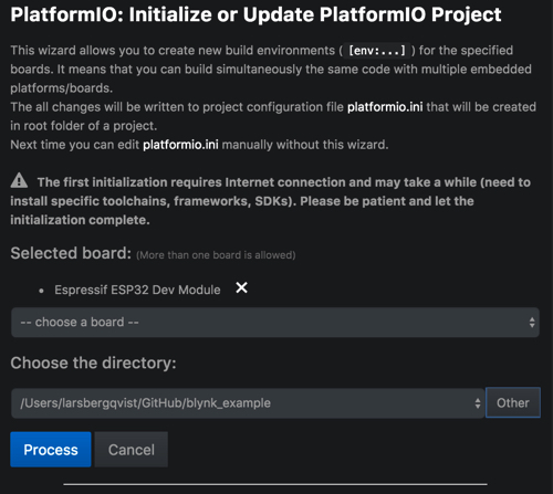
In Atom/PlatformIO, select PlatformIO->Initialize or Update PlatformIO project. Select ESP32 Dev Module as board and choose a folder for your project:
Next, let’s define the dependencies in the platformio.ini file. We need the blynk-library for connecting to the Blynk server and the Adafruit_Sensor- and DHT-sensor-libraries for reading the DHT11-sensor:
This file contains hidden or bidirectional Unicode text that may be interpreted or compiled differently than what appears below. To review, open the file in an editor that reveals hidden Unicode characters.
Learn more about bidirectional Unicode characters
| [env:esp32dev] | |
| platform = espressif32 | |
| board = esp32dev | |
| framework = arduino | |
| lib_deps= | |
| https://github.com/blynkkk/blynk-library | |
| https://github.com/adafruit/Adafruit_Sensor | |
| https://github.com/adafruit/DHT-sensor-library | |
Next, create a new cpp-file in the src-folder in your project. Give it any name, e.g. blynk_example.cpp. Also, create a header file called credentials.h.
I like to keep credentials in a separate file so I don’t commit passwords and other secrets to GitHub. In credentials.h, change auth to the auth token from the Blynk project and set ssid and password so that it fits your WiFi environment.
This file contains hidden or bidirectional Unicode text that may be interpreted or compiled differently than what appears below. To review, open the file in an editor that reveals hidden Unicode characters.
Learn more about bidirectional Unicode characters
| // You should get Auth Token in the Blynk App. | |
| // Go to the Project Settings (nut icon). | |
| char auth[] = "a89e439b754d4d9888ecaa74c7b0e61a"; | |
| // Your WiFi credentials. | |
| // Set password to "" for open networks. | |
| char ssid[] = "YOUR WIFI SSID"; | |
| char pass[] = "YOUR WIFI PASSWORD"; |
The setup() and loop() for the project looks like this:
This file contains hidden or bidirectional Unicode text that may be interpreted or compiled differently than what appears below. To review, open the file in an editor that reveals hidden Unicode characters.
Learn more about bidirectional Unicode characters
| void setup() | |
| { | |
| Serial.begin(9600); | |
| pinMode(BEEP_PIN, OUTPUT); | |
| dht.begin(); | |
| Blynk.begin(auth, ssid, pass, IPAddress(192,168,1,16),8442); | |
| timer.setInterval(TIMER_INTERVAL, timerEvent); | |
| } | |
| void loop() | |
| { | |
| Blynk.run(); | |
| timer.run(); | |
| } |
setup() sets a pin to output for a beep signal, starts the dht-sensor, connects with the Blynk-server and creates a timer that should be called at a regular interval (to sample temperature values).
loop() makes a call to the Blynk server and runs the timer.
The rest of the code in the project contains initializations and callbacks:
This file contains hidden or bidirectional Unicode text that may be interpreted or compiled differently than what appears below. To review, open the file in an editor that reveals hidden Unicode characters.
Learn more about bidirectional Unicode characters
| #include <Arduino.h> // Arduino basic stuff | |
| #include <WiFi.h> // WiFi-library needed for Blynk | |
| #include <WiFiClient.h> | |
| #include <BlynkSimpleEsp32.h> // Include Blynk library | |
| #include "credentials.h" // Keep WiFi and Blynk credentials in a separate file | |
| // | |
| // BEEP/BUZZER | |
| // Called when the value of V1 is written to the Blynk server | |
| // V1 is connected to a button in the GUI. When the button is pressed, the V1=1 | |
| // and when it is released V1=0 | |
| // | |
| #define BEEP_PIN 17 | |
| BLYNK_WRITE(V1) | |
| { | |
| int pinValue = param.asInt(); | |
| Serial.print("V1 value is: "); | |
| Serial.println(pinValue); | |
| if (pinValue == 1) | |
| { | |
| digitalWrite(BEEP_PIN, HIGH); | |
| } | |
| else | |
| { | |
| digitalWrite(BEEP_PIN, LOW); | |
| } | |
| } | |
| // | |
| // DHT Sensor setup | |
| // | |
| #include <Adafruit_Sensor.h> | |
| #include <DHT.h> | |
| #define DHTPIN_INDOOR 16 | |
| #define DHTTYPE_INDOOR DHT11 | |
| DHT dht(DHTPIN_INDOOR, DHTTYPE_INDOOR); | |
| // | |
| // Use a timer to trigger reading of the sensor every 5 seconds | |
| // Write the value to V2 to send it to the Blynk server | |
| // | |
| BlynkTimer timer; | |
| #define TIMER_INTERVAL 5000 | |
| void timerEvent() | |
| { | |
| float temperature = dht.readTemperature(); | |
| if (!isnan(temperature)) | |
| { | |
| Serial.println(temperature); | |
| Blynk.virtualWrite(V2, temperature); | |
| } | |
| } |
BLYNK_WRITE(V1) is called when the virtual pin V1 is changed on the server. This happens when the button in the mobile app’s GUI is pressed or released. If the button is pressed, a HIGH signal will be sent on GPIO 17. This will make a sound on the active piezo buzzer.
The timerEvent() method is called every 5 seconds, gets the temperature from the DHT11 via GPIO 16 and writes it to virtual pin V2. This will update the displayed value in the mobile app.
You can let the Blynk mobile project operate directly with GPIO pins, but using virtual pins gives more control on what should happen.
The complete project can be found on GitHub:
https://github.com/LarsBergqvist/blynk_example
Testing the project
With the Blynk server running and the ESP32-project code uploaded to the board, it is time to test the setup with the Blynk app:
Open the project in the Blynk app. Press the play icon. The app will now try to connect to the Blynk server and the ESP32-board. Press the Beep-button. If everything is setup correctly, the buzzer connected to the ESP32 should make a sound. Every five seconds, a temperature value from the DHT11 should be sent to the mobile app.

This was my first experiment with Blynk with a very simple example. Head over to the Blynk site for more information and ideas.

I want to use a slider in blynk app for a pin of esp32 developmentboard.In the pin section of slider,it shows to select only “Virtual pin (like V0. V1, V2, ….V100,…).But i didn’t find any virtual pin in esp32 board.Any one can help me to understand virtual or how can i use a SLIDER of BLYNK APP for ESP32 board.
LikeLike