
The Arduino computers are excellent for reading sensor data, and they are so inexpensive and consume very little power that you can use plenty of them in your home without breaking your wallet.
The Raspberry on the other hand, is more powerful, a bit pricier, but can easily be programmed to perform more challenging tasks like storing data and hosting a web server.
What if your Arduinos (the Major Toms) could report their sensor measurements to the Raspberry (Ground Control) in a simple way? Then you could access and analyze all measurements via a Web interface on the Raspberry (using a mobile phone e.g.)
This blog post describes my setup for sending sensor data via the 433 MHz band to the Raspberry.
The gadgets
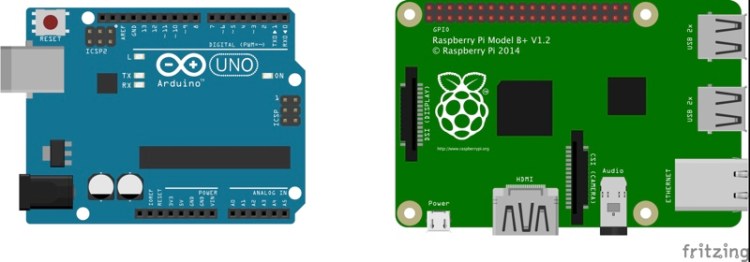
Computers
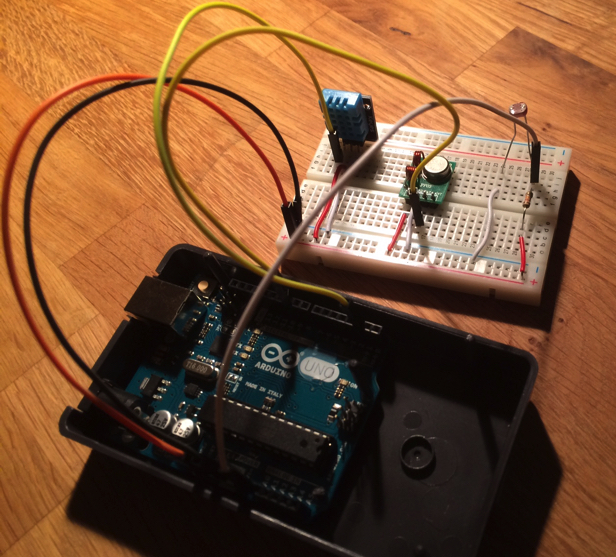
I use an Arduino UNO for sensor measurements and a Raspberry Pi 2 B+ as receiver of sensor data. The RPi uses Raspbian as OS.
Radio transmitter- and receiver
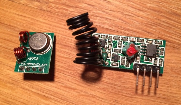
A 5V 433 MHz transmitter/receiver pair costs less than 100 SEK so it is a very affordable way to make your devices wireless. The pair I bought worked nicely with both Arduino and Raspberry.
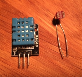
Sensors
As input data I used a 3-pin module for measuring temperature and humidity (DHT11) and a Light Dependent Resistor (LDR) for getting an indicator of light level. The DHT11 only provides integer precision on measurements, but that’s good enough for my experiment.
The RCSwitch library
Instead of inventing my own RF communication protocol, I have used RCSwitch which is an open-source library that can be used on both Arduinos and RPi:s.
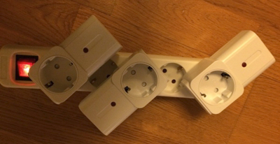
The main purpose of RCSwitch is to handle reading and writing of data from/to RC controlled home sockets. It works like a breeze with even the cheapest RC sockets I could find (3 sockets for 129 SEK in Sweden). You can for example sniff the control signals from the remote and let an Arduino send the signals instead. I tested this with an Arduino that sent a repeating sequence of on/off signals to the 3 sockets. Could be used for an EDM relay noise percussion orchestra, but let’s leave that for another post :-).
RCSwitch is stable and reliable and can be used for other purposes as well. You can use it for sending custom data between Arduinos and RPi:s for example.
I wanted my Arduino to send sensor data for recording on my Raspberry. To get this to work, there were a few things with the RCSwitch protocol that needed to be handled:
- There is no handshaking mechanism (just fire & forget), so the transmitter (the Arduino) will need to do multiple transmits of each measurement to make sure that at least one reaches the destination.
- The receiver (the Raspberry) needs to check that it only stores each measurement once.
- Some sort of check sum and sanity check of the data is needed so that signals from other 433 MHz devices are not interpreted as Arduino measurements. 433 MHz signals can also be noisy, so that’s a reason for extra control of the data as well.
To keep things simple, I decided that a complete measurement should fit into 4 bytes as 32 bits is the maximum size for a single RCSwitch message. We need a measurement type identifier, actual data and a checksum so I decided to divide the 4 bytes like this:
- byte 3: (bits 4-7): The type id of the measurement (value 0-15) so that the receiver knows how to interpret the data.
- byte 3: (bit 0-4): A rolling sequence number (value 0-15) so that the receiver can identify multiple transmits of the same message).
- byte 1 & 2: The actual sensor data, (value 0-1023)
- byte 0: A checksum of byte 1-3 (value 0-255)
Setting up the Arduino
Install the RCSwitch library
The easiest way to get the RCSwitch library in place for the Arduino IDE is to clone the repo from GitHub and copy it to Arduino’s library folder on the computer where you use the Arduino IDE.
Install the DHT sensor library
If you want to use a DHT sensor module for temperature and humidity, there is a DHT sensor library available that you can download from within the Arduino IDE.
Setup the hardware
The Arduino handles the transmitter module. The module gets a 5V- and ground connections from the Arduino pins. The input to the transmitter is the yellow cable (from PWM output pin 10 on the Arduino). As a sensor I use a photo resistor (LDR) in a voltage divider circuit. The varying voltage before the photo resistor goes to to Analog In Pin 0 on the Arduino (via the long white cable in the image below). The long green cable in the image acts as antenna for the transmitter and is attached to the antenna pin on the transmitter module.
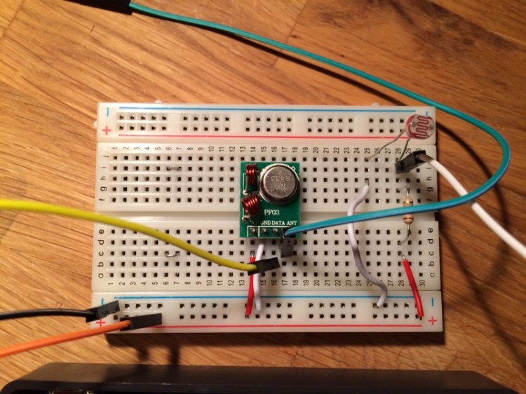
The DHT module is setup with ground (right pin) and 5 V (middle pin) from the Arduino. The output signal comes from the left pin and goes to digital pin 2 on the Arduino.
Setting up the Raspberry Pi
Setting up Pi switch
On the Pi side, I wanted to use Python, so I had a go with Pi Switch. Pi Switch is a wrapper around RCSwitch (C++) which provides RCSwitch functionality in Python form for the Raspberry. To get Pi Switch in place, there are a few dependencies that need to be installed. The Readme for Pi Switch explains all the details. I wanted to use Python 3.* for this project, but I could not get a proper libboost version for 3.* so I had to stay with Python 2.*.
Pi Switch and RCSwitch on the Raspberry use Wiring Pi to access the GPIO pins. Wiring Pi does not use the BCM standard for pin numbering, so you need to study this mapping table to wire up the Raspberry correctly.
Setting up the RPi hardware
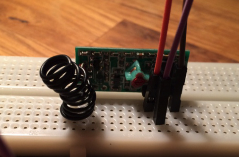
For the receiver I use 3.3V and ground from the Raspberry. The received signal goes to BCM GPIO pin 27 on my RPi2 (note that this is WiringPi pin 2 in Pi Switch!!). I first wired 5V to the receiver, but as this might generate a 5V output signal to the non-5v tolerant RPi input pin, I switched to 3.3V as voltage feed for the receiver.
Program the Arduino
For the Arduino program, we first need to include the dependencies to RCSwitch and DHT. The Arduino loop reads a sensor, package the measurement data as a 32-bit word with type identifier and checksum and transmits the data as a 433 MHz signal with the help of RCSwitch. Temperature and humidity are float values from the DHT library, but I cast them to integers (and lose some precision) to make the message encoding easier. The DHT11 has integer precision, so the casting does not matter in this case. With a better sensor, the float value 0.0 – 100.0 could be transformed to a two byte value before transmission and then be transformed back to a float value on the receiver side.
This file contains hidden or bidirectional Unicode text that may be interpreted or compiled differently than what appears below. To review, open the file in an editor that reveals hidden Unicode characters.
Learn more about bidirectional Unicode characters
| #include "RCSwitch.h" | |
| #include <DHT.h> | |
| #define LIGHT_IN 0 // Light measurement goes to A0 pin | |
| #define DHTPIN 2 // Signal in from DHT11 goes to digital pin 2 | |
| #define DHTTYPE DHT11 | |
| // Unique ID:s (4 bits, 0-15) for each measurement type so that the receiver | |
| // understands how to interpret the data on arrival | |
| #define LDR_MEASUREMENT_ID 1 | |
| #define TEMP_MEASUREMENT_ID 2 | |
| #define HUMIDITY_MEASUREMENT_ID 3 | |
| #define TX_PIN 10 // PWM output pin to use for transmission | |
| #define DELAY_BETWEEN_TRANSMITS 5000 // in milliseconds | |
| DHT dht(DHTPIN, DHTTYPE); | |
| RCSwitch transmitter = RCSwitch(); | |
| void setup() | |
| { | |
| Serial.begin(9600); | |
| pinMode(LIGHT_IN, INPUT); | |
| transmitter.enableTransmit(TX_PIN); | |
| transmitter.setRepeatTransmit(25); | |
| } | |
| // A rolling sequence number for each measurement | |
| // Restarts at 0 after seqNum=15 has been used | |
| unsigned long seqNum=0; | |
| unsigned long Code32BitsToSend(int measurementTypeID, unsigned long seq, unsigned long data) | |
| { | |
| unsigned long checkSum = measurementTypeID + seq + data; | |
| unsigned long byte3 = ((0x0F & measurementTypeID) << 4) + (0x0F & seq); | |
| unsigned long byte2_and_byte_1 = 0xFFFF & data; | |
| unsigned long byte0 = 0xFF & checkSum; | |
| unsigned long dataToSend = (byte3 << 24) + (byte2_and_byte_1 << 8) + byte0; | |
| return dataToSend; | |
| } | |
| unsigned long previousTime = 0; | |
| void loop() | |
| { | |
| unsigned long currentTime = millis(); | |
| if (currentTime – previousTime <= DELAY_BETWEEN_TRANSMITS) | |
| { | |
| return; | |
| } | |
| previousTime = currentTime; | |
| // Get the light measurement (0-1023) | |
| unsigned int data = analogRead(LIGHT_IN); | |
| unsigned long dataToSend = Code32BitsToSend(LDR_MEASUREMENT_ID,seqNum,data); | |
| // Send 32 bits of data | |
| transmitter.send(dataToSend, 32); | |
| delay(2000); | |
| unsigned long t = (unsigned long)dht.readTemperature(); | |
| dataToSend = Code32BitsToSend(TEMP_MEASUREMENT_ID,seqNum,t); | |
| if (!isnan(t)) | |
| { | |
| transmitter.send(dataToSend, 32); | |
| } | |
| delay(2000); | |
| unsigned long h = (unsigned long)dht.readHumidity(); | |
| dataToSend = Code32BitsToSend(HUMIDITY_MEASUREMENT_ID,seqNum,h); | |
| if (!isnan(h)) | |
| { | |
| transmitter.send(dataToSend, 32); | |
| } | |
| seqNum++; | |
| if (seqNum > 15) | |
| { | |
| seqNum = 0; | |
| } | |
| } |
Program the Raspberry
When the Arduino is up and running and have started sending data, the receiver can be started on the Raspberry. It is a Python program that (within an eternal loop) polls pi_switch for a received value. The Python program needs to be started with superuser privileges for accessing the GPIO pins:
sudo python receiver.py
To handle multiple transmits of the same measurement, I have a simple check that the new received value is different from the previous one. If several Arduinos would send asynchronous messages, this approach would not work, but for this example with synchronous messages from only one Arduino, this check is sufficient.
When a message has been accepted it needs to be decoded. It’s the same bit manipulation as in the Arduino program, but in reverse. When the separate parts of the 32-bit word has been fetched, a checksum control and additional sanity checks are made so that noise and interference from other 433 MHz transmitters are less likely to cause incorrectly recorded data.
This file contains hidden or bidirectional Unicode text that may be interpreted or compiled differently than what appears below. To review, open the file in an editor that reveals hidden Unicode characters.
Learn more about bidirectional Unicode characters
| # Uses pi_switch from https://github.com/lexruee/pi-switch-python | |
| # See pi_switch readme for details on setup | |
| from pi_switch import RCSwitchReceiver | |
| import time | |
| receiver = RCSwitchReceiver() | |
| receiver.enableReceive(2) | |
| acceptedTypes = { 1 : "Light", 2 : "Temp [C]", 3: "Humidity [%]" } | |
| prev_value = 0L | |
| while True: | |
| if receiver.available(): | |
| value = receiver.getReceivedValue() | |
| if value == prev_value: | |
| # we have already seen this measurement, so ignore it | |
| continue | |
| # decode byte3 | |
| byte3 = (0xFF000000 & value) >> 24 | |
| typeID = int((0xF0 & byte3) >> 4) | |
| seqNum = int((0x0F & byte3)) | |
| # decode byte2 and byte1 | |
| data = int((0x00FFFF00 & value) >> 8) | |
| # decode byte0 | |
| checkSum = int((0x000000FF & value)) | |
| calculatedCheckSum = 0xFF & (typeID + seqNum + data) | |
| # Sanity checks on received data | |
| correctData = True | |
| if calculatedCheckSum != checkSum: | |
| # print("Incorrect checksum!") | |
| correctData = False | |
| elif data > 1023: | |
| # print("Incorrect data!") | |
| correctData = False | |
| elif typeID not in acceptedTypes: | |
| # print("Incorrect ID!") | |
| correctData = False | |
| elif seqNum > 15: | |
| # print("Incorrect SeqNum") | |
| correctData = False | |
| if correctData: | |
| print(str.format("{0}: {1}={2} SeqNum={3}",time.ctime(),acceptedTypes[typeID],data,seqNum)) | |
| prev_value = value | |
| receiver.resetAvailable() | |
Testing
When I tested the setup I noticed that the 433 MHz signal was quite sensitive to noise. A higher voltage and a better antenna for the transmitter would probably help. Still, with a noisy signal, using repeated transmits and having a checksum- and sanity check on the receiver side filtered out most of the noise.
I also tested interfering with a 433 MHz remote control.
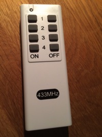
The simple checksum found that these messages were not valid and rejected the values.
An output from the receiver looks like this (I exhaled on the DHT and covered the photo resistor to cause some changes in the sensor input):
pi@raspberrypi:~/GitHub/ArduinoToRaspberry_via_433MHz_RF/Raspberry $ sudo python receiver.py
Tue Mar 15 22:00:05 2016: Humidity [%]=30 SeqNum=9
Tue Mar 15 22:00:07 2016: Light=231 SeqNum=10
Tue Mar 15 22:00:10 2016: Temp [C]=24 SeqNum=10
Tue Mar 15 22:00:14 2016: Humidity [%]=30 SeqNum=10
Tue Mar 15 22:00:15 2016: Light=254 SeqNum=11
Tue Mar 15 22:00:19 2016: Temp [C]=24 SeqNum=11
Tue Mar 15 22:00:23 2016: Humidity [%]=30 SeqNum=11
Tue Mar 15 22:00:24 2016: Light=264 SeqNum=12
Tue Mar 15 22:00:28 2016: Temp [C]=24 SeqNum=12
Tue Mar 15 22:00:32 2016: Humidity [%]=30 SeqNum=12
Tue Mar 15 22:00:33 2016: Light=225 SeqNum=13
Tue Mar 15 22:00:37 2016: Temp [C]=24 SeqNum=13
Tue Mar 15 22:00:40 2016: Humidity [%]=30 SeqNum=13
Tue Mar 15 22:00:42 2016: Light=668 SeqNum=14
Tue Mar 15 22:00:45 2016: Temp [C]=24 SeqNum=14
Tue Mar 15 22:00:49 2016: Humidity [%]=46 SeqNum=14
Tue Mar 15 22:00:51 2016: Light=226 SeqNum=15
Tue Mar 15 22:00:54 2016: Temp [C]=24 SeqNum=15
Tue Mar 15 22:00:58 2016: Humidity [%]=37 SeqNum=15
Tue Mar 15 22:00:59 2016: Light=250 SeqNum=0
Final words
The code for this project can be fetched from GitHub at https://github.com/LarsBergqvist/ArduinoToRaspberry_via_433Mhz_RF
Future enhancements for this project would be to store the received data in a database and expose it as graphs via a web interface.
It would also be nice to be able to chain 32-bit messages into longer sequences so that Major Tom could (after reading an appropriate sensor) send the words:
Planet Earth is blue
And there’s nothing I can do
to Ground Control.
Tinker on!

2 Thoughts