
This blog post describes how I have set up a door-open detector at home. It uses a small ATtiny85 board that broadcasts a 433 MHz signal every time the door is opened. The signal is fetched by a Raspberry Pi that in turn publishes an MQTT message that results in the event being stored in a database and also being re-published to a cloud service. The circuit is only active when the door is open (and in that state only consumes 10mA), so the whole setup can be driven by a battery pack that is bound to last for a very long time.
Background
I have a reed switch that I originally planned to use for turning on the hall lights when opening the front door. I have not yet found the perfect light source for this project, so while my quest for the ultimate welcome-home-lamp continues I decided to use the reed switch for an experiment with registrations of door-open events at home. My first idea was to use an ESP8266 board wired to the reed sensor. But as the purpose is only to trigger a simple event and as the ESP8266 consumes at least 70mA when active, I opted for a simpler processor and board – an ATtiny85 processor on an USB board. This is a very small and inexpensive board (about $5), but it does not have WiFi capabilities. So how to communicate the events? No worries! With a 433 MHz transmitter ($2.5), the ATtiny85 board can send a radio signal to my outlet-powered Raspberry Pi that can transform the event to an IP-based message. The circuit in this setup uses about 10mA when active, but when the door is closed, the circuit draws no energy at all. As I hate re-charging batteries, this is an option that fits me.
The gear
The board is a Digispark USB clone and it can be programmed via the Arduino IDE (see below). The transmitter and receiver are the cheapest possible, but I have found these to be very reliable if wires are added as antennas.

The door-open detector kit consist of a magnet and a reed switch with connections for Normally-Closed or Normally-Opened. I use Normally-Closed (NC) connection. This means that the reed switch is closed when no magnet is nearby (i.e. when the door is open). When the magnet is close, the switch is open (i.e. when the door is closed).

Working with the Digispark USB board
ATtiny85 is an inexpensive 8-bit AVR-processor from Atmel. It has 8kB flash memory, 512B EEPROM and 512 B SRAM and can be powered with voltages between 2.7 and 5.5 V which gives a maximum operating frequency of 20 MHz. For easy programming via the Arduino IDE, you can use the chip mounted on a development board like the Digispark USB. Here are some useful links for getting started with the Digispark USB board:
https://digistump.com/wiki/digispark/tutorials/connecting
https://github.com/digistump/DigistumpArduino/
http://www.electroschematics.com/12102/learn-to-use-attiny85-usb-mini-development-board/
Wiring
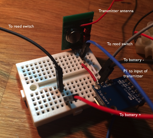
The wiring is very simple. A battery pack provides power to the Digispark board and the RF transmitter, but the current goes through a reed switch that is “normally closed”, i.e. the circuit is only closed when the door magnet is far from the switch.

On my prototype board, the setup looks like this:
The RF receiver is connected to my Raspberry Pi 3. I use the same setup and the same Python script that I developed for this project:
The Arduino IDE sketch
The Arduino sketch for the Digispark USB board uses the RCSwitch library for sending a coded 32-bit 433MHz signal when the program starts. As there is no handshake with the receiver, I send the message three times to increase the likelihood that the receiver gets the message. For avoiding that a message is registered several times by the receiver, the message contains a rolling sequence number. This way, the receiver can detect duplicates. As the Digispark board is shutdown when the door is closed, I store the previously used sequence number in EEPROM so that it can be read the next time the board is booted (the next time the door is opened). I use a magic number (42) as first byte in the EEPROM memory to note that a sequence number is available.
This file contains bidirectional Unicode text that may be interpreted or compiled differently than what appears below. To review, open the file in an editor that reveals hidden Unicode characters.
Learn more about bidirectional Unicode characters
| // A sketch for a DigiSpark USB device that detects when a door is opened | |
| // The door should have a reed switch with NC (normally closed) connected to the Vin wire of the device | |
| // When the door is opened, the reed switch is closed and the device is started | |
| // A 32-nit message is then sent via a 433 MHz signal that can be picked up by an appropriate receiver | |
| // (a Raspberry Pi in my case). | |
| // When the door is closed, the reed switch is opened and the device is shut down | |
| // | |
| // Depends on the RCSwitch library https://github.com/sui77/rc-switch | |
| // and the eeprom-library | |
| // | |
| #include "RCSwitch.h" | |
| #include <EEPROM.h> | |
| // Unique ID:s (4 bits, 0-15) for each measurement type so that the receiver | |
| // understands how to interpret the data on arrival | |
| #define DOOR_MEASUREMENT_ID 4 | |
| #define TX_PIN 1 // PWM output pin to use for transmission | |
| // A rolling sequence number for each measurement so that the receiver can handle duplicate data | |
| // Restarts at 0 after seqNum=15 has been used. Stored in EEPROM between restarts of the device. | |
| byte seqNum=0; | |
| RCSwitch transmitter = RCSwitch(); | |
| void setup() | |
| { | |
| if ( EEPROM.read(0) == 42 ) | |
| { | |
| // We have stored the previously used sequence number in EEPROM | |
| seqNum = EEPROM.read(1); | |
| } | |
| seqNum++; | |
| if (seqNum > 15) | |
| { | |
| seqNum = 0; | |
| } | |
| EEPROM.write(0,42); | |
| EEPROM.write(1,seqNum); | |
| transmitter.enableTransmit(TX_PIN); | |
| transmitter.setRepeatTransmit(25); | |
| } | |
| bool valueHasBeenSent = false; | |
| void loop() | |
| { | |
| if (!valueHasBeenSent) | |
| { | |
| // Send the message several times to increase | |
| // detection by the receiver | |
| sendDoorOpenSignal(seqNum); | |
| delay(2000); | |
| sendDoorOpenSignal(seqNum); | |
| delay(2000); | |
| sendDoorOpenSignal(seqNum); | |
| delay(2000); | |
| valueHasBeenSent = true; | |
| } | |
| } | |
| void sendDoorOpenSignal(int sequenceNumber) | |
| { | |
| // use alternating bits for the value for better reliability | |
| unsigned long valueToSend = 0b0101010; | |
| unsigned long dataToSend = code32BitsToSend(DOOR_MEASUREMENT_ID,sequenceNumber,valueToSend); | |
| transmitter.send(dataToSend, 32); | |
| } | |
| unsigned long code32BitsToSend(int measurementTypeID, unsigned long seq, unsigned long data) | |
| { | |
| unsigned long checkSum = measurementTypeID + seq + data; | |
| unsigned long byte3 = ((0x0F & measurementTypeID) << 4) + (0x0F & seq); | |
| unsigned long byte2_and_byte_1 = 0xFFFF & data; | |
| unsigned long byte0 = 0xFF & checkSum; | |
| unsigned long dataToSend = (byte3 << 24) + (byte2_and_byte_1 << 8) + byte0; | |
| return dataToSend; | |
| } |
Raspberry Pi programming
(Additional note, August 2017: as the pi-switch library has been deprecated, I now use an ESP8266 with RCSwitch as signal receiver for transforming events to MQTT messages. See Addendum below for more details).
On the Raspberry Pi side, there is a 433MHz receiver and Python script that uses the pi-switch library for listening to signals. It is the same script and protocol that I used in this post for radio communication between an Arduino and a Raspberry Pi:
except that, in this case, when receiving a door open signal, an MQTT message is constructed and published.
This file contains bidirectional Unicode text that may be interpreted or compiled differently than what appears below. To review, open the file in an editor that reveals hidden Unicode characters.
Learn more about bidirectional Unicode characters
| # Uses pi_switch from https://github.com/lexruee/pi-switch-python | |
| # See pi_switch readme for details on setup | |
| from pi_switch import RCSwitchReceiver | |
| import time | |
| import paho.mqtt.client as mqtt | |
| receiver = RCSwitchReceiver() | |
| receiver.enableReceive(2) | |
| def publish_message(): | |
| # Initialize the client that should connect to the Mosquitto broker | |
| client = mqtt.Client() | |
| connOK=False | |
| while(connOK == False): | |
| try: | |
| print("try connect") | |
| client.connect("192.168.1.16", 1883, 60) | |
| connOK = True | |
| except: | |
| connOK = False | |
| time.sleep(2) | |
| client.publish("Home/Frontdoor/Opened","1.0") | |
| time.sleep(5) | |
| client.disconnect() | |
| acceptedTypes = { 1 : "Light", 2 : "Temp [C]", 3: "Humidity [%]", 4: "Door open" } | |
| prev_value = 0L | |
| while True: | |
| if receiver.available(): | |
| value = receiver.getReceivedValue() | |
| if value == prev_value: | |
| # we have already seen this measurement, so ignore it | |
| continue | |
| # decode byte3 | |
| byte3 = (0xFF000000 & value) >> 24 | |
| typeID = int((0xF0 & byte3) >> 4) | |
| seqNum = int((0x0F & byte3)) | |
| # decode byte2 and byte1 | |
| data = int((0x00FFFF00 & value) >> 8) | |
| # decode byte0 | |
| checkSum = int((0x000000FF & value)) | |
| calculatedCheckSum = 0xFF & (typeID + seqNum + data) | |
| # Sanity checks on received data | |
| correctData = True | |
| if calculatedCheckSum != checkSum: | |
| correctData = False | |
| elif data > 1023: | |
| correctData = False | |
| elif typeID not in acceptedTypes: | |
| correctData = False | |
| elif seqNum > 15: | |
| correctData = False | |
| if correctData: | |
| print(str.format("{0}: {1}={2} SeqNum={3}",time.ctime(),acceptedTypes[typeID],data,seqNum)) | |
| prev_value = value | |
| if (typeID == 0x04): | |
| publish_message() | |
| receiver.resetAvailable() | |
The MQTT message is fetched by the subscribers that I have in my home MQTT setup. See this post series for details:
One subscriber stores the data locally and another one forwards the message to an external cloud service.
So with this setup in place and the reed switch and magnet mounted on the front door, I get a registration of every door open event in a MongoDB database (visualized on the local LAN with my chart app, https://larsbergqvist.wordpress.com/2016/07/10/a-web-app-for-iot-data-visualization/) and externally on Adafruit IO.
With the message stored in Adafruit IO, you can use IFTTT to generate a trigger like an email alert when the door is opened. Nice to have when away and wanting to have an eye on the door. But very irritating when the kids run in-and-out when you’re at home :-).

The code for this project can be cloned from GitHub:
https://github.com/LarsBergqvist/door_open_detector
Addendum, August 2017
I have modified the original setup of this project slightly. I finally found a nice LED-stripe that I have mounted at the top of the door. The detector setup now uses a relay to switch on this light source when the door is opened (it still sends a 433MHz signals so that the opening event is registered). I have also switched from a Digispark board to an Ardunio Nano to get more I/O pins and easier programming. See this Arduino IDE-project:
As the pi-switch library has been deprecated, I have replaced my Raspberry Pi with an ESP8266-board as a 433MHz event detector. The ESP8266 has a 433MHz receiver module and listens for incoming signals. It then transforms the events to IP-based MQTT messages. See this repository:
https://github.com/LarsBergqvist/Bridging_433MHz_To_MQTT
and this blog post:
The Sensor433 library and Geeetech transmitters and receivers

Hi.
Does this listening process use a lot of cpu power? I have a automation system running on a RPi, an all inputs and outputs are Esp8266 modules, comunicating over mqtt (mosquitto mqtt running on the same Rpi), and I’m thinking about using some comercial 433.92 PIR Sensors and Reed switchs, sending data directly to my raspberry pi, but i’m concerned about high cpu usage…
Thanks.
LikeLike
Hi Daniel! The radio-listener on my RPi3 uses about 3-5% of the CPU. I currently have a slightly different listener (https://larsbergqvist.wordpress.com/2016/10/26/radio-chirp-data-incorporated-in-an-mqtt-environment/) but it uses pi-switch in the same way as described in this blog post.
LikeLike
Hi Lars.
Good idea and good project. Have you measured the power consumption of the detector ? Is it powered with battery or with the domestic power ? I’m adding a wireless remote on an existing desktop lamp for my daughter and wonder if the autonomy will be sufficient with the li-po cell i’ve choiced.
LikeLike
Thanks for your kind comment, David. The ATtiny85 setup consumes about 10mA while the the door is open (and no energy at all while the door is closed). If the door is open for a total of a few minutes every day, a small battery with 1000mAh capacity will last for many months.
My installed project is modified nowadays. I use an Arduino Nano, a 433MHz transmitter and a relay to send signals and also turn on some lights in the hall when the door is opened. The board still draws around 10-15mA while the door is open (the lights connected to the relay have separate power trough an outlet and a 12V adaptor).
For my battery-powered sensor nodes I put the board to sleep between measurements so that the power consumption gets very low. See for example https://larsbergqvist.wordpress.com/2017/03/26/the-sensor433-library-and-geeetech-transmitters-and-receivers/.
I am not using battery powered signal detectors, though. My 433Mhz signals are received by either a Raspberry Pi or an ESP8266-board connected to outlets via adaptors.
I guess one can save energy on a signal receiving Arduino-like board by putting it to sleep for short amounts of time (with the Narcoleptic library for example) between listening for incoming signals. The receiver needs to responsive though. A good overview of power-saving Arduinos can be found in this article: http://www.home-automation-community.com/arduino-low-power-how-to-run-atmega328p-for-a-year-on-coin-cell-battery/
I hope this gives you some ideas.
LikeLike
RC-Switch has a retransmit value. It defaults to 10. You can change that instead of sending multiple times.
LikeLike
Thanks for reading and thanks for the tip! I use additional retransmits with delays inbetween for increasing the probability that the signal is registered by the receiver. With my setup, this configuration worked best.
LikeLike