
Internet-of-things does not require that every device has to be directly connected to the Internet. The complexity and possible security issues with every sensor having its own IP address would in fact be overwhelming. A better approach would be to use more light-weight protocols for the sensor and actuator data and locally aggregate and filter these data at common points before making them available on the Internet. In this post I will describe a theory and implementation of transmitting small radio chirp messages from an Arduino Pro mini and then receive these data on a Raspberry Pi for transformation to MQTT messages for the Internet.
Background
For some time now, I have experimented with IoT-nodes at home for doing automation and collecting data. With empirical learning from this, I have found a way to scale IoT-nodes in a simple, pragmatic and inexpensive way. Meanwhile I have also read Rethinking the Internet of things by Francis daCosta:

It contains a more extensive and formalized description of parts that I found out by experience, so I will borrow some terminology from this book. BTW, the book is worth reading and you can get the ebook edition for free from ApressOpen: http://www.apress.com/gp/book/9781430257400
An example architecture for collecting sensor data
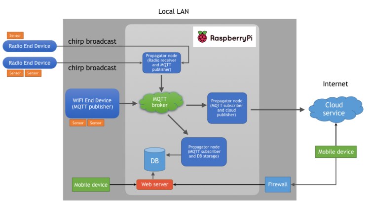
Data (e.g. temperature) is collected by a sensor connected to an IoT end device (e.g. an Arduino board) – they are at the far end of the IoT network – and several sensors can be attached to the same device. The end device makes a minimal chirp message of the data and broadcasts it wirelessly. Simple devices can use radio messages (I use 433MHz transmitters) and more complex end devices (like an ESP8266 board) can publish messages over WiFi.
The 433 MHz radio protocol has no acknowledge of received data, so missed or duplicated messages on the receiver side can happen. Thus, this light-weight communication protocol suites scenarios where the data is non-critical. For example, if we have a device that broadcasts the current indoor house temperature every 15 minutes, a missed or duplicated data point is unlikely to cause any trouble or disasters.
IoT propagator nodes listens for chirp messages, filters/selects data of interest, aggregates it and make a transform into MQTT IP packages for the local network. A higher-level propagator node subscribes to these messages and when receiving data it executes some actions. The actions could be further propagation of the message from the LAN to Internet and/or store the data locally.
So, the main idea is to use as simple end devices/sensor nodes as possible and then propagate the information upwards in the “value chain” where more advanced handling of the data can be added at every step.
The collected data can be consumed by mobile devices by accessing a web application on the local LAN or by interacting with a cloud service (e.g. Adafruit IO) that has got a copy of the data. This is the final step where the most advanced node (a human being) analyzes the data.
I have covered local MQTT environments in some previous posts, so I will not go into detail about subscribers and publishers here. Check out these texts instead:
- A self-hosted MQTT environment for IoT – part 1
- A self-hosted MQTT environment for IoT – part 2
- A self-hosted MQTT environment for IoT – part 3
An example implementation
As an example implementation I will use an Arduino Pro Mini (3.3V edition) as IoT-end device. It uses a BMP180 pressure/temperature sensor and has a 433 MHz radio transmitter. I chose this Arduino model as it can easily be made to consume very little power when idling. By using a sleep library and removing the “on”-led on the board, the required current while idling is only 0.25mA – that’s ok for running the device on batteries. The power consumption can be reduced even further, but for my purpose, this is sufficient.

The cost for this IoT-end device is:
Arduino Pro Mini 3.3V (OpenSmart) = $4
BMP180 sensor (Keyestudio) = $4
433 MHz transmitter (noname) = $3
battery holder + wires = $3
That is, around $14 in total, and the parts can be reused for other projects (I have not included my re-chargeable AA-batteries in the budget above as I expect to be using them for several hundred charge cycles).
The propagator nodes are implemented as services with Python on a Raspberry Pi 3. The RPi has a 433 MHz receiver and WiFi connected to the local LAN.

My RPi 3 is setup with a 433 MHz receiver and a transmitter. The transmitter is used for sending data to IoT-nodes with actuators, but as this post is about a sensor scenario, I will not cover the RPi transmitter in this text (if you are curious, you can read more in this post https://larsbergqvist.wordpress.com/2016/05/15/rcswitch-revisited-control-rc-outlets-with-a-web-app/).
The 433 MHz communication protocol
The data that is sent over 433 MHz radio is handled by the RCSwitch library on the Arduino and the pi-switch library on the Raspberry Pi. These libraries support sending and receiving data to/from RC outlets and remote controls but can be used for other purposes. I have used the libraries in previous posts for communication between devices, for example in this one:
RCSwitch uses 32 bits / 4 bytes for a message – this is my chirp! I only use two bytes for the actual sensor data, the other two bytes are used for data identification and a checksum.
My chirp can contain an encoded unsigned two byte integer value from a sensor. The whole 32 bit message looks like this in that case:

Thus, sensor values between 0 and 65535 can be sent.
My protocol also supports sending signed float values with two decimals. In that case I multiply the value by 100 and store the data in two bytes. The highest bit is a sign flag that indicates if the value is positive or negative. This way, float values between -327,67 and +327,67 can be sent.

By looking at the sensor id, the receiver knows if the data should be treated as an unsigned integer or a signed float value (so the sender and the receiver have to agree on what the different sensor id:s mean). By extending the sender- and receiver side, additional data types can be implemented – e.g. a signed two byte integer (values between -32767 and +32767).
Arduino implementation
The sketch for the Arduino Pro Mini in the Arduino IDE looks like this:
This file contains hidden or bidirectional Unicode text that may be interpreted or compiled differently than what appears below. To review, open the file in an editor that reveals hidden Unicode characters.
Learn more about bidirectional Unicode characters
| // | |
| // An Arduino sketch for an IoT node that broadcasts sensor values via | |
| // 433 MHz radio signals | |
| // The RCSwitch library is used for the transmissions | |
| // The Narcopleptic library is used for power save during delay | |
| // Sensor values are fetched from an BPM180/085 sensor via i2C | |
| // | |
| #include <Wire.h> | |
| #include <Adafruit_BMP085.h> | |
| #include "RCSwitch.h" | |
| #include <Narcoleptic.h> | |
| #define CLIENT_NAME "TopFloorClient" | |
| #define TX_PIN 10 // PWM output pin to use for transmission | |
| // | |
| // Sensor setup | |
| // The BMP085 module measure ait pressure and temperature and operates via i2C | |
| // | |
| Adafruit_BMP085 bmp; // pin 4, SDA (data), pin 5, SLC (clock) | |
| // | |
| // Data transmission setup | |
| // | |
| #define TOPFLOOR_TEMP_ID 1 | |
| #define BMP_PRESSURE_ID 2 | |
| RCSwitch transmitter = RCSwitch(); | |
| void setup() | |
| { | |
| Serial.begin(9600); | |
| bmp.begin(); | |
| transmitter.enableTransmit(TX_PIN); | |
| transmitter.setRepeatTransmit(25); | |
| } | |
| unsigned long seqNum=0; | |
| void loop() | |
| { | |
| float temp = bmp.readTemperature(); | |
| Serial.print("Temperature = "); | |
| Serial.print(temp); | |
| Serial.println(" *C"); | |
| unsigned int encodedFloat = EncodeFloatToTwoBytes(temp); | |
| unsigned long dataToSend = Code32BitsToSend(TOPFLOOR_TEMP_ID,seqNum,encodedFloat); | |
| TransmitWithRepeat(dataToSend); | |
| float pressure = bmp.readPressure(); | |
| unsigned int pressureAsInt = pressure/100; | |
| Serial.print("Pressure = "); | |
| Serial.print(pressureAsInt); | |
| Serial.println(" hPa"); | |
| dataToSend = Code32BitsToSend(BMP_PRESSURE_ID,seqNum,pressureAsInt); | |
| TransmitWithRepeat(dataToSend); | |
| for (int i=0; i< 100; i++) | |
| { | |
| // Max narcoleptic delay is 8s | |
| Narcoleptic.delay(8000); | |
| } | |
| seqNum++; | |
| if (seqNum > 15) | |
| { | |
| seqNum = 0; | |
| } | |
| } | |
| unsigned long Code32BitsToSend(int measurementTypeID, unsigned long seq, unsigned long data) | |
| { | |
| unsigned long checkSum = measurementTypeID + seq + data; | |
| unsigned long byte3 = ((0x0F & measurementTypeID) << 4) + (0x0F & seq); | |
| unsigned long byte2_and_byte_1 = 0xFFFF & data; | |
| unsigned long byte0 = 0xFF & checkSum; | |
| unsigned long dataToSend = (byte3 << 24) + (byte2_and_byte_1 << 8) + byte0; | |
| return dataToSend; | |
| } | |
| // Encode a float as two bytes by multiplying with 100 | |
| // and reserving the highest bit as a sign flag | |
| // Values that can be encoded correctly are between -327,67 and +327,67 | |
| unsigned int EncodeFloatToTwoBytes(float floatValue) | |
| { | |
| bool sign = false; | |
| if (floatValue < 0) | |
| sign=true; | |
| int integer = (100*fabs(floatValue)); | |
| unsigned int word = integer & 0XFFFF; | |
| if (sign) | |
| word |= 1 << 15; | |
| return word; | |
| } | |
| void TransmitWithRepeat(unsigned long dataToSend) | |
| { | |
| transmitter.send(dataToSend, 32); | |
| Narcoleptic.delay(2000); | |
| transmitter.send(dataToSend, 32); | |
| Narcoleptic.delay(2000); | |
| } |
The sketch uses the Narcoleptic library to save power while idling. As the maximum delay time for this library is 8 seconds, I need a loop around repeated delay calls to achieve an idling time of around 15 minutes.
The rolling sequence number for each measurement is used so that the receiver can detect duplicate data. To increase the likelihood of a message reaching the receiver, the message is sent several times. If a receiver gets a sequence of identical data (including the same sequence number), then it knows that the messages are duplicates and not just the same sensor values sent at different points in time.
Raspberry Pi implementation
For the propagator node implementation, there are some prerequisites:
- Python 2.* installed
- The Python pi-switch library installed
- A running MQTT broker somewhere (I use a mosquitto broker running on the Raspberry Pi)
I have a PropagatorApplication that acts as an IoT-propagator node. It is started with a runserver.py script:
This file contains hidden or bidirectional Unicode text that may be interpreted or compiled differently than what appears below. To review, open the file in an editor that reveals hidden Unicode characters.
Learn more about bidirectional Unicode characters
| #!/usr/bin/env python | |
| from propagatornode.propagatorapplication import PropagatorApplication | |
| if __name__ == '__main__': | |
| wiringPiPinForReceiver = 2 | |
| brokerIP = "192.168.1.16" | |
| brokerPort = 1883 | |
| app = PropagatorApplication(wiringPiPinForReceiver,brokerIP,brokerPort) | |
| app.run() |
The script initializes the application with the pin to use for the 433 MHz receiver and the address for the broker where the transformed messages should be published.
The application defines what chirp messages to listen to and what MQTT topic they should be mapped to. A RadioListener class is used for fetching and decoding the radio chirp messages and an MQTTpublisher class is used for publishing the transformed message:
This file contains hidden or bidirectional Unicode text that may be interpreted or compiled differently than what appears below. To review, open the file in an editor that reveals hidden Unicode characters.
Learn more about bidirectional Unicode characters
| # | |
| # A propagator node in an MQTT System | |
| # It listens on messages/chirps via 433MHz radio and translates them to | |
| # MQTT packages that are published over TCP/IP to a broker | |
| # | |
| from measurementtype import MeasurementType | |
| from MQTTpublisher import MQTTpublisher | |
| from radiolistener import RadioListener | |
| import time | |
| class PropagatorApplication: | |
| wiringPiPinForReceiver = 2 | |
| brokerIP = "" | |
| brokerPort = 1883 | |
| def __init__(self,wiringPiPinForReceiver,brokerIP,brokerPort): | |
| self.wiringPiPinForReceiver = wiringPiPinForReceiver | |
| self.brokerIP = brokerIP | |
| self.brokerPort = brokerPort | |
| def run(self): | |
| # Defines the radio listener that uses pi-switch to listen to messages | |
| # over 433 MHz radio | |
| validMeasurementTypes = [ | |
| MeasurementType(1,"Temp","float","Home/TopFloor/Temperature"), | |
| MeasurementType(2,"Pressure(hPa)","int","Home/TopFloor/Pressure"), | |
| MeasurementType(3,"DoorOpened","int","Home/FrontDoor/Status") | |
| ] | |
| radioListener = RadioListener(self.wiringPiPinForReceiver,validMeasurementTypes) | |
| # Defines the publisher that publishes MQTT messages to a broker | |
| publisher = MQTTpublisher(self.brokerIP,self.brokerPort) | |
| while True: | |
| if radioListener.newMessageAvailable(): | |
| message = radioListener.getLatestMessage() | |
| if message is not None: | |
| # Take the radio message and publish the data as an MQTT message | |
| publisher.postMessage(message.getTopic(),str(message.getValue())) | |
| time.sleep(1) | |
The RadioListener uses pi-switch for listening to radio messages and doing the bit operations needed for decoding a message:
This file contains hidden or bidirectional Unicode text that may be interpreted or compiled differently than what appears below. To review, open the file in an editor that reveals hidden Unicode characters.
Learn more about bidirectional Unicode characters
| from radiomessage import RadioMessage | |
| from measurementtype import MeasurementType | |
| from pi_switch import RCSwitchReceiver | |
| class RadioListener: | |
| validMeasurementTypes = [] | |
| previousValue = 0 | |
| numIdenticalValuesInARow = 0 | |
| latestMessage = None | |
| receiver = RCSwitchReceiver() | |
| def __init__(self,wiringPiPinForReceiver,validMeasurementTypes): | |
| wiringPiPinForReceiver | |
| self.validMeasurementTypes = validMeasurementTypes | |
| self.receiver.enableReceive(wiringPiPinForReceiver) | |
| def newMessageAvailable(self): | |
| if self.receiver.available(): | |
| value = self.receiver.getReceivedValue() | |
| self.latestMessage = self.getMessageFromDecodedValue(value) | |
| self.receiver.resetAvailable() | |
| if (self.latestMessage is None): | |
| return False | |
| else: | |
| return True | |
| def getMessageFromDecodedValue(self,value): | |
| if value == self.previousValue: | |
| self.numIdenticalValuesInARow += 1 | |
| else: | |
| self.numIdenticalValuesInARow = 1 | |
| # decode byte3 | |
| byte3 = (0xFF000000 & value) >> 24 | |
| typeID = int((0xF0 & byte3) >> 4) | |
| seqNum = int((0x0F & byte3)) | |
| # decode byte2 and byte1 | |
| data = int((0x00FFFF00 & value) >> 8) | |
| # decode byte0 | |
| checkSum = int((0x000000FF & value)) | |
| # calculate simple check sum | |
| calculatedCheckSum = 0xFF & (typeID + seqNum + data) | |
| # Sanity checks on received data | |
| correctData = True | |
| if calculatedCheckSum != checkSum: | |
| correctData = False | |
| elif seqNum > 15: | |
| correctData = False | |
| message = None | |
| if correctData: | |
| self.previousValue = value | |
| if self.numIdenticalValuesInARow == 2: | |
| # only store a value if an identical value was detected twice | |
| # if detected more than two times, ignore the value | |
| measurementType = self.getMeasurementTypeFromId(typeID) | |
| if measurementType is None: | |
| # invalid typeID | |
| print("Invalid type id") | |
| self.latestMessage = None | |
| else: | |
| message = RadioMessage(measurementType, data) | |
| return message | |
| def getMeasurementTypeFromId(self,typeID): | |
| measurementType = next(i for i in self.validMeasurementTypes if i.id == typeID) | |
| return measurementType | |
| def getLatestMessage(self): | |
| return self.latestMessage | |
The MQTTpublisher class wraps the code needed for publishing a message to an MQTT broker:
This file contains hidden or bidirectional Unicode text that may be interpreted or compiled differently than what appears below. To review, open the file in an editor that reveals hidden Unicode characters.
Learn more about bidirectional Unicode characters
| import paho.mqtt.client as mqtt | |
| import time | |
| class MQTTpublisher: | |
| brokerIP = "" | |
| brokerPort = 0 | |
| def __init__(self,brokerIP,brokerPort): | |
| self.brokerIP = brokerIP | |
| self.brokerPort = brokerPort | |
| def postMessage(self,topic,message): | |
| print("Publishing message " + message + " on topic " + topic) | |
| # Initialize the client that should connect to the Mosquitto broker | |
| client = mqtt.Client() | |
| connOK=False | |
| print("Connecting to " + self.brokerIP + " on port " + str(self.brokerPort)) | |
| while(connOK == False): | |
| try: | |
| print("try connect") | |
| client.connect(self.brokerIP, self.brokerPort, 60) | |
| connOK = True | |
| except: | |
| connOK = False | |
| time.sleep(2) | |
| client.publish(topic,message) | |
| print("Publish done") | |
| client.disconnect() | |
The complete code for this experiment can be fetched from GitHub: https://github.com/LarsBergqvist/IoT_chirps_to_MQTT
Conclusions
Using an IoT-end device without IP connection has several benefits. It is less expensive and consumes less power than a device with a TCP/IP-stack. The device is also resilient to hacking (the radio messages can be compromised, but depending on the application and the smartness of the propagator nodes, this might not be an issue).
By aggregating and filtering data from many devices at one or a few propagator nodes, it is easier to adapt the system (what messages to actually store etc) and let’s you have one single point where data are pushed out to the Internet (this approach is beneficial regardless if TCP/IP or radio messages are used for the IoT-end devices).
Due to the simplicity of the proposed radio protocol, it will not suite all applications. To send larger chunks of data, a more complex end device is needed. But, when a large “swarm” of devices for simple measurements is needed, I prefer using radio-based IoT-end devices.

One thought